Installing a high‑inertia servomotor like the Bosch Rexroth MSK101E‑0450‑NN‑S1‑AG0‑NNNN calls for the same attention to detail that went into its design. From uncrating to first jog, every step influences both personal safety and long‑term performance. The following guide walks through a full installation sequence, weaving in the factory data and torque values supplied by Rexroth so that your engineering or maintenance team can reference actionable numbers rather than generalities.
- Know the Hardware Before You Lift It
- Pre‑Installation Inspection and Site Preparation
- Mechanical Mounting—Torque Numbers That Matter
- Electrical Connections—Ground First, Then Power, Then Feedback
- Initial Commissioning With the Drive
- Functional Safety and Environmental Integrity
- Final Checklist Before Hand‑Over
- When Things Go Sideways
Know the Hardware Before You Lift It
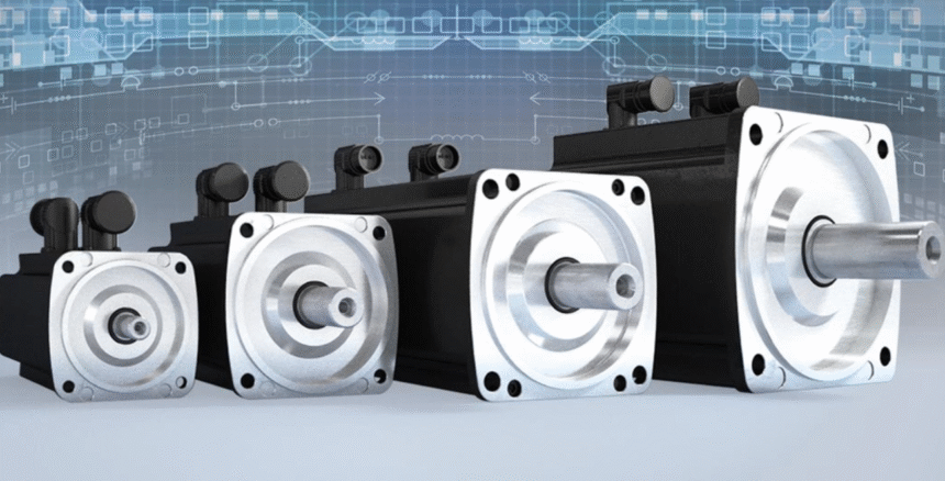
The MSK101E frame weighs roughly 53.5 kg and stretches 501 mm from flange to end cap, with a centering diameter of 180 mm and a 192 mm square flange. Internally it supplies 80.5 Nm of continuous stall torque, can surge to 231 Nm intermittently, and draws up to 39 A at standstill, all while relying on natural‑convection cooling. In practice these facts dictate three immediate safety considerations:
- Lifting gear must be rated for at least 60 kg and should pick from the housing—not the shaft—to keep the 14‑millimetre shaft within its axial load envelope.
- Ambient flow is the only heat‑sink. Crowding the housing with cable trays or brackets invites hotspots that degrade winding insulation.
- Drive sizing and overcurrent limits must accommodate peak current of 262 A, or the drive will trip during aggressive acceleration profiles.
Pre‑Installation Inspection and Site Preparation
Qualified personnel—familiar with NFPA 70E standards and local lock‑out/tag‑out policy—should open the crate. Inspect the shaft keyway, Hiperface single‑turn encoder connector, and the IP65 radial shaft seal. Any abrasive dust or moisture discovered at this stage can resemble normal shipping grime, yet inside the seal it gives rise to premature leakage.
Review the IndraDyn‑S manual in its entirety before moving forward; Rexroth expressly warns that motors are not to be energized until the supplied documentation is understood. Place the motor on vibration‑absorbing blocks near its final resting position and confirm that mounting dimensions on the machine match the flange or foot pattern shown in the OEM drawing.

Mechanical Mounting—Torque Numbers That Matter
Rexroth provides specific screw classes and tightening torques for the MSK family. When flange‑mounting a 101‑frame unit, select M10 × 30, property class 8.8 socket‑head screws and torque them to 48 Nm (μK = 0.12). If foot‑mounting is required, observe the same M10/48 Nm combination at each footpad bolt.
Align the motor so that the shaft centerline forms a straight line with the load’s shaft. Soft‑foot is unacceptable; use feeler gauges to verify the flange is flush. The plain shaft is balanced with the full key installed, so couple only to transmission elements that are likewise full‑key balanced. Apply heat‑shrink or thermal rings if you must expand a pulley: hammering on the shaft violates Rexroth’s prohibition against axial strikes.
Once seated, rotate the shaft by hand. Any gritty sensation implies misalignment or foreign debris and must be corrected before the power stage is connected.
Electrical Connections—Ground First, Then Power, Then Feedback
De‑energize the entire machine, discharge the drive DC link, and verify absence of dangerous voltage with a properly rated meter. Rexroth’s warning to open connectors only in a de‑energized state exists for a reason.
Terminal Box and Power Leads
The MSK101E ships with an A‑side rotatable power connector. Remove the terminal‑box lid, ensuring the O‑ring is intact. Torque the adapter‑plate screws to 9 Nm ± 10 %, the U‑V‑W clamp screws to 2.5 Nm, and the PE stud to 3.8 Nm. Replace the lid with all screws thread‑locked at 6.5 Nm to maintain the IP65 seal.
Route the motor power cable separately from encoder and brake leads to minimize EMI. The cable’s armor or braided shield must land at the drive’s PE bar—not at cabinet back‑panel paint—so that high‑frequency common‑mode currents flow harmlessly to ground.
Encoder Link
The optical Hiperface encoder provides 128 signal periods and must be seated squarely to avoid checksum errors at boot . Engage the bayonet lock until it clicks; finger‑tight is insufficient for the IP rating.
Initial Commissioning With the Drive
Populate the IndraDrive parameter set with the motor’s type code and nameplate values, paying special attention to:
- Continuous current (I_cont = 39 A)
- Motor thermal time constant (per Rexroth table)
- Resolver/encoder type (single‑turn Hiperface)
Execute a phasing routine so the drive learns the commutation offset. Jog at low speed with the load uncoupled; listen for cogging or howl that signals incorrect phasing. Once verified, ramp the speed to rated 4500 rpm while monitoring phase current and housing temperature. Natural‑convection units are intolerant of blocked airflow, so an infrared camera scan of the stator end bells during this run is worthwhile.
Functional Safety and Environmental Integrity
If the machine falls under IEC 61508 or ISO 13849, integrate the motor’s Safe Torque Off through the drive rather than building external contactor logic. Although the MSK101E lacks a holding brake, vertical axes can be guarded with a redundant electromechanical brake mounted on the load shaft.
Where wash‑down or food‑grade requirements apply, place the conduit entry downward and install a condensation loop. Sealing air accessories (SUP‑M01‑MSK or SUP‑M02‑MSK) are available for over‑pressure protection in dusty zones; Rexroth specifies G 1/8‑inch pipe threads and limits connection torque to 14–15 Nm to avoid stripping the cast‑aluminum port.
Final Checklist Before Hand‑Over
Confirm that:
- All mounting and connector screws meet documented torque values.
- Phase resistance and insulation‑resistance tests match factory tolerances.
- Shaft run‑out is within 0.02 mm TIR at the coupling hub.
- Drive fault log is clear after a cold start.
- Thermal sensor read‑back corresponds to ambient plus expected rise.
Sign off and release the axis to production. Record the installation date, torque values, and parameter set in the CMMS so a technician years from now can reconstruct what was done and why.
When Things Go Sideways
Even the most diligent teams occasionally face bearing noise, encoder drift, or drive overcurrent. Wake Industrial stocks factory‑new and expertly refurbished MSK101E‑series motors and offers rapid repair turnaround that restores OEM alignment and encoder calibration while replacing seals, bearings, and cable glands. Engineers and plant managers across North America trust Wake Industrial for replacement or repair. To get a repair quote call 1-919-443-0207 or email [email protected].